Subwoofer Wiring Diagrams
The backbone of a robust auditory experience is the subwoofer, and when wired correctly, a subwoofer can substantially augment your audio system’s low-frequency output. It’s not easy and there are many permutations, so for a subwoofer wiring diagram to fit your needs, read on…
Welcome to our comprehensive guide, where we cover everything from 1 ohm to 8 ohm, and one or multiple subwoofers. In this Subwoofer Wiring Diagram guide, we shed light on the intricate layouts of each one.
We discuss the implications of parallel and series wiring and differentiate between Dual Voice Coil (DVC) and Single Voice Coil (SVC) subwoofers. By mastering these wiring layouts, you can tailor your sound system to match any external amplifier.
1 x 1 Ohm Dual Voice Coil (DVC) Subwoofer – Wiring Diagram
To start, we’ll focus on the wiring diagrams for a single 1 Ohm DVC subwoofer. When it comes to DVC subwoofers, you have two primary wiring options – parallel and series. Your choice between these two methods will depend on your amplifier’s capabilities and the desired load impedance.
Option 1: Parallel Wiring – 0.5 Ohm Load
With parallel wiring, both voice coils are wired together, side by side. This method decreases the overall load impedance of your setup. So, when two 1 Ohm coils are wired in parallel, the result is a 0.5 Ohm load.
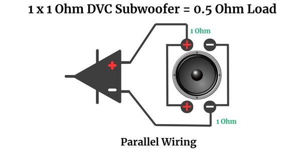
In this configuration, you’ll need an amplifier that is stable at a 1/2 Ohm. Do note that not all amplifiers can handle such a low impedance load, so ensure that your amplifier is capable of this before wiring your subwoofer in this manner.
Failure to match the subwoofer load with the amplifier’s capability could result in overheating and potential damage to your audio equipment.
Option 2: Series Wiring – 2 Ohm Load
Series wiring, on the other hand, involves connecting the voice coils in a chain. One after the other. This method increases the overall load impedance. So, for a 1 Ohm DVC subwoofer wired in series, you’ll end up with a 2 Ohm load.
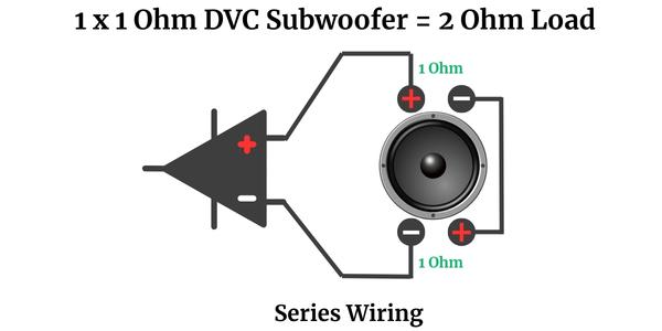
Here, your choice of amplifier should ideally be stable at 2 Ohms mono or 1 Ohm mono. As with parallel wiring, it’s crucial to ensure your amplifier can handle this load. Proper impedance matching is vital for the health and performance of your audio system.
Remember, understanding your equipment’s capabilities and matching them accurately is key to building an optimal audio system. Now, let’s crank up the bass and enjoy the immersive sound experience brought to you by properly wired subwoofers!
2 x 1 Ohm DVC Subwoofers – Wiring Diagrams
When dealing with multiple subwoofer, particularly DVC models, wiring can become a bit more complex. However, with a solid understanding and clear diagrams to guide you, you can optimize your setup for the best sound quality. Let’s take a look at the wiring diagrams for 2 x 1-ohm DVC subwoofers.
Option 1: Series/Parallel Wiring – 1 Ohm Load
In a series/parallel configuration for 2 x 1-ohm subwoofers, each sub’s voice coils are wired in series, and then the subwoofers themselves are wired together in parallel. This configuration effectively balances the load impedance across your system. This means, when you wire two 1 Ohm DVC subs in series/parallel, the overall load is 1 Ohm.
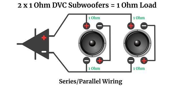
For this configuration, you would ideally use an amplifier that’s stable at 1 Ohm mono. Remember, always check your amplifier’s stability ratings to ensure it can handle the load impedance. The right match between your subs and amplifier is key to prevent overheating and possible damage to your audio equipment.
Option 2: Series Wiring – 4 Ohm Load
In a series configuration, both the voice coils and the subwoofers themselves are wired in series. This method increases the load impedance. So, wiring two 1 Ohm DVC subs in series results in a 4 Ohm load.
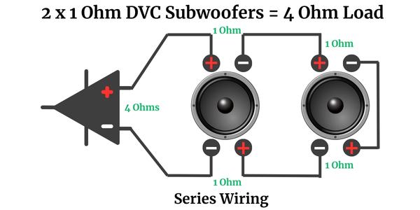
With this setup, your amplifier should ideally be stable at 4 Ohms. However, amplifiers that are stable at 2 or 1 Ohm mono will also be compatible with this setup. As always, it’s important to double-check your amplifier’s stability ratings to ensure that it can handle the load impedance.
To optimize your audio system’s performance and longevity, understanding your equipment’s capabilities and pairing them properly is essential. With the right configuration, you’re well on your way to an immersive, room-filling sound experience!
1 x 2 Ohm Dual Voice Coil (DVC) Subwoofer – Wiring Diagram
When working with a single 2 Ohm DVC subwoofer, wiring can be done in either parallel or series configuration. The choice between these configurations will depend on the amplifier’s capabilities and the desired load impedance. Let’s delve into the specific wiring diagrams and instructions for each of these setups.
Option 1: Parallel Wiring – 1 Ohm Load
In parallel wiring, both voice coils are wired together side by side. This method reduces the overall load impedance. So, when you wire a 2 Ohm DVC subwoofer’s voice coils in parallel, you achieve a 1 Ohm load.
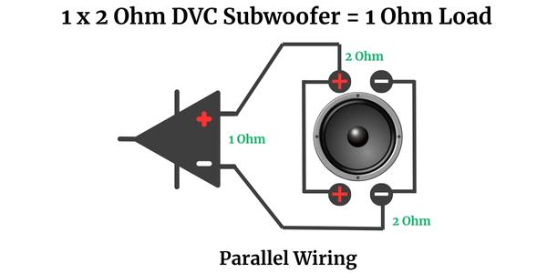
For this setup, the ideal amplifier is one that is stable at 1 Ohm. Please note that not all amplifiers can handle such low impedance loads. Hence, before wiring your subwoofer in this manner, ensure that your amplifier can manage this load to prevent potential damage or overheating of your audio equipment.
Option 2: Series Wiring – 4 Ohm Load
Series wiring involves connecting the voice coils in a chain – one after the other. This method increases the overall load impedance. So, if you wire a 2 Ohm DVC sub’s voice coils in series, you’ll end up with a 4 Ohm load.
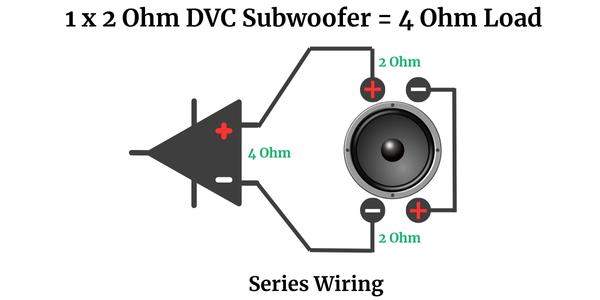
With this setup, your amplifier should ideally be stable at 4 Ohms. That said, amplifiers that are stable at 2 or 1 Ohm mono are also compatible with this setup. Always ensure that your amplifier can handle this load to maintain the health and performance of your audio system.
By understanding these wiring configurations and matching them accurately to your amplifier’s capabilities, you can create an optimal audio system. This will offer an immersive listening experience, whether you’re jamming to your favorite music or sinking into a movie night at home.
2 x 2 Ohm DVC Subwoofers – Wiring Diagrams
Wiring multiple subs, specifically dual voice coil models, can seem daunting at first, but follow these diagrams and you’ll soon be sorted. In this section, we’ll explore the wiring diagrams for 2 x 2 Ohm DVC subwoofers. The two primary wiring options we will focus on are parallel/parallel and series/series.
Option 1: Parallel Wiring – 0.5 Ohm Load
In a parallel/parallel configuration, the voice coils of each subwoofer are wired in parallel, and then the subs themselves are wired together in parallel. This configuration decreases the load impedance across your audio system. So, when two 2 Ohm DVC subwoofers are wired in parallel/parallel, you achieve a 0.5 Ohm load.
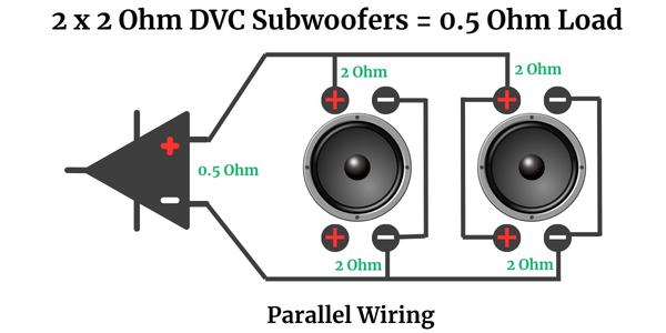
For this configuration, you need an amplifier that is stable at 1/2 Ohm mono. Please note that not all amplifiers can handle such low impedance loads, so it’s vital to ensure your amplifier is compatible before wiring your subwoofers in this manner. Mis-matching can lead to overheating or damage to your audio equipment.
Option 2: Series Wiring – 8 Ohm Load
In series wiring, voice coils are connected one after the other, which increases the total load impedance. When you wire all the voice coils of two 2 Ohm DVC subwoofers in series, you end up with an 8 Ohm load.
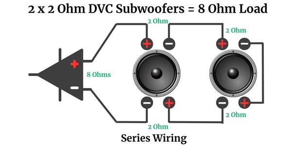
For this configuration, your amplifier should ideally be stable at 8 Ohms mono. However, amplifiers that are stable at lower impedances, such as 4, 2, or 1 Ohm mono, can also work with this setup. As always, it’s crucial to confirm your amplifier’s stability ratings to ensure it can comfortably manage the load impedance, safeguarding your audio equipment and maintaining optimum performance.
Navigating the different wiring configurations can seem daunting, but understanding their impact on load impedance and amplifier stability enables you to optimize your audio system’s performance. With this understanding, you can create an audio setup that delivers high-quality sound, enriching your audio experience!
1 x 4 Ohm DVC Subwoofer – Wiring Diagrams
In this section, we will delve into the wiring diagrams for a single 4 Ohm Dual Voice Coil subwoofers. We’ll discuss two main wiring options: parallel and series. Your choice between these methods will depend on your amplifier’s specifications and the load impedance you aim to achieve. Let’s take a closer look at each option.
Option 1: Parallel Wiring – 2 Ohm Load
Parallel wiring involves wiring the voice coils together, side by side. This method decreases the overall load impedance. So, when you wire a 4 Ohm DVC subwoofer’s voice coils in parallel, you get a 2 Ohm load.
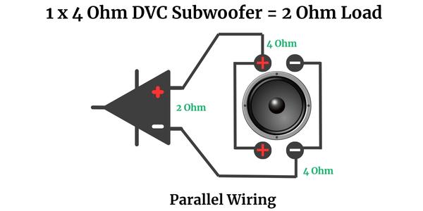
For this setup, an ideal amplifier would be one that is stable at 2 Ohm mono or 1 Ohm mono. Remember, it’s crucial to confirm that your amplifier can handle the impedance load to prevent potential overheating or damage to your audio equipment.
Option 2: Series Wiring – 8 Ohm Load
Series wiring, on the other hand, involves connecting the voice coils one after the other. This method increases the overall load impedance. So, if you wire a 4 Ohm DVC subwoofer’s voice coils in series, you end up with an 8 Ohm load.
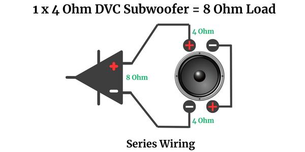
For this series setup, your amplifier should ideally be stable at 8 Ohms. However, amplifiers that are stable at 4, 2, or 1 Ohm would also be compatible with this setup. As always, checking your amplifier’s stability ratings is crucial to ensure it can handle the load impedance.
By understanding these wiring configurations and accurately matching them to your amplifier’s capabilities, you can create an optimal sound system.
2 x 4 Ohm DVC Subwoofers – Wiring Diagrams
When configuring multiple subwoofers, particularly dual voice coil models, the wiring process can get a bit intricate, so follow these subwoofer wiring diagrams carefully. In this section, we’ll explore the wiring diagrams for 2 x 4 Ohm DVC subwoofers, focusing on two main configurations: parallel/parallel and series/parallel.
Option 1: Parallel Wiring – 1 Ohm Load
In a parallel setup, the voice coils of each sub are wired in parallel, and then the subwoofers themselves are also wired together in parallel. This arrangement decreases the load impedance across your system. When you wire two 4 Ohm DVC subwoofers in a fully parallel setup, you achieve a 1 Ohm load.
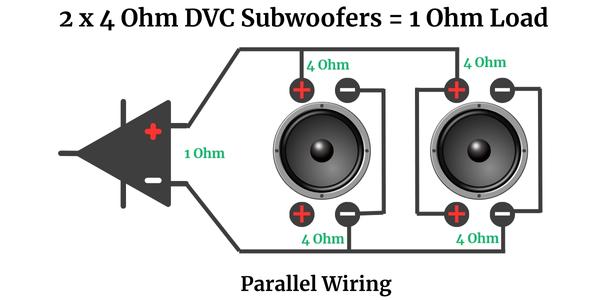
For this configuration, you need an amplifier that is stable at 1 Ohm mono. It’s worth noting that not all amplifiers can handle such low impedance loads. So, before wiring your subwoofers in this manner, ensure your amplifier can accommodate this load to avoid potential overheating or damage to your audio equipment.
Option 2: Series/Parallel Wiring – 4 Ohm Load
In a series/parallel configuration, the voice coils of each subwoofer are wired in series, and then they’re wired together in parallel. This setup effectively balances the load impedance across your audio system. This means when you wire two 4 Ohm DVC subwoofers in a series/parallel configuration, the overall load remains at 4 Ohms.
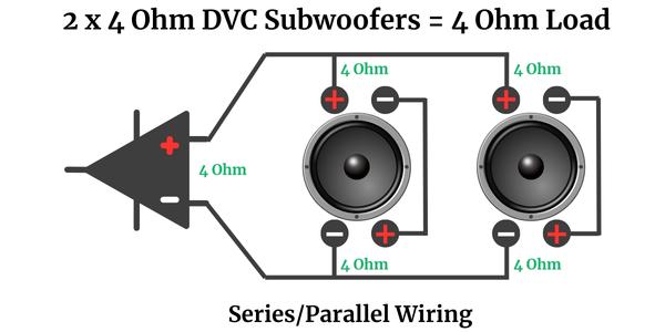
In this scenario, your amplifier should ideally be stable at 4 Ohms. However, amplifiers that are stable at 2 or 1 Ohm are also compatible with this setup. As always, double-check your amplifier’s stability ratings to ensure it can handle the load impedance.
Understanding your audio equipment’s capabilities and ensuring the correct pairing between your speakers and amplifier is key to achieving optimal sound quality. Armed with this knowledge, you’re all set for an enhanced, immersive audio experience!
2 x 4 Ohm Single Voice Coil (SVC) Subwoofers – Wiring Diagrams
Setting up multiple subwoofers involves a deeper understanding of your audio equipment’s properties and the wiring configurations available. In this section, we will explore the wiring diagrams for two 4 Ohm Single Voice Coil (SVC) subwoofers, detailing the parallel and series wiring options.
Option 1: Parallel Wiring – 2 Ohm Load
In parallel wiring, the subwoofers are wired side by side, effectively reducing the total load impedance. So, when you wire two 4 Ohm SVC subs in parallel, the overall load becomes 2 Ohms.
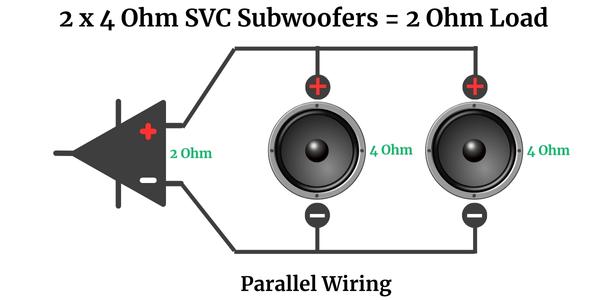
For this setup, your amplifier should ideally be stable at 2 Ohms. Amplifiers stable at 1 Ohm will also be compatible with this setup. Always remember to check your amplifier’s stability ratings to ensure it can handle the load impedance to avoid potential overheating or damage to your audio system.
Option 2: Series Wiring – 8 Ohm Load
In series wiring, the subwoofers are connected one after the other, which increases the total load impedance. If you wire two 4 Ohm SVC subwoofers in series, you’ll end up with an 8 Ohm load.
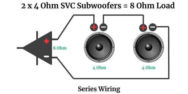
As you can see in the above wiring diagram, with this setup, your amplifier should ideally be stable at 8 Ohms. However, amplifiers that are stable at 4, 2, or 1 Ohm mono would also work with this configuration. As always, ensure to match the amplifier’s capabilities with the load impedance to maintain the performance and health of your audio system.
By understanding these wiring configurations and matching them to your amplifier’s capabilities, you can create an efficient audio system that delivers superior sound quality. Whether you’re a music enthusiast or a movie lover, the right audio setup can significantly enhance your listening experience.
One 6 Ohm DVC Subwoofer – Wiring Diagrams
Remember, DVC subwoofers offer multiple wiring configurations, each affecting the overall impedance of your system differently. In this section, we will delve into the wiring diagrams for a 6 Ohm DVC speaker and discuss parallel and series wiring options.
Option 1: Parallel Wiring – 3 Ohm Load
In a parallel wiring setup, the voice coils are wired side by side. This configuration decreases the total load impedance across the system. So, when you wire the voice coils of a 6 Ohm DVC subwoofer in parallel, you achieve a 3 Ohm load.

For this configuration, the amplifier you use should ideally be stable at 3 Ohms. But, amplifiers stable at lower impedance levels, such as 2 or 1 Ohm, will also work with this setup. As always, remember to verify your amplifier’s stability ratings to ensure that it can comfortably handle the load impedance.
Option 2: Series Wiring – 12 Ohm Load
In a series wiring setup, the voice coils are wired one after the other. This configuration increases the total load impedance across your system. Therefore, when you wire the voice coils of a 6 Ohm DVC subwoofer in series, you end up with a 12 Ohm load.
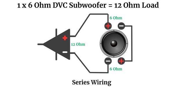
For this series setup, your amplifier should ideally be stable at 12 Ohms. However, amplifiers that are stable at lower impedances, such as 4, 2, or 1 Ohm mono, would also work with this configuration. As always, ensure to match the amplifier’s capabilities with the load impedance to maintain the performance and health of your audio system.
Understanding the implications of your wiring configurations and ensuring the correct match between your subs and amplifier is key to achieving optimal sound quality. With this knowledge in hand, you’re ready to enjoy a superior audio experience!
2 x 6 Ohm DVC Subwoofers – Wiring Diagrams
This section presents the wiring diagrams for 2 x 6 Ohm DVC subs, focusing on parallel/parallel and series/parallel configurations.
Option 1: Parallel Wiring – 1.5 Ohm Load
Parallel wiring entails connecting the voice coils or subwoofers side by side, thereby decreasing the total load impedance. This means that when you wire two 6 Ohm DVC subwoofers in parallel, the combined load becomes 1.5 Ohms.
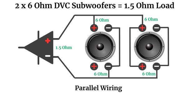
For this setup, your amplifier should ideally be stable at 1 Ohm mono, which will comfortably handle the load impedance and maintain system performance. Always verify your amplifier’s stability ratings to protect your audio equipment from potential damage.
Option 2: Series/Parallel Wiring – 6 Ohm Load
In series/parallel wiring, the voice coils are wired in series (one after the other), and the subs are wired in parallel. This combination results in a levelled load impedance. So, w you wire the 6 Ohm voice coils in series and the subs themselves in parallel, you achieve a 6 Ohm load.
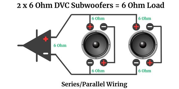
For this setup, your amplifier should ideally be stable at 6 Ohms. However, amplifiers stable at lower impedances, such as 4, 2, or 1 Ohm, would also work with this configuration. As always, check your amplifier’s stability ratings to ensure optimal performance and longevity of your audio system.
By understanding these configurations and correctly matching your amplifier’s capabilities, you can create an efficient audio system that offers outstanding sound quality.
1 x 8 Ohm SVC Subwoofer – Wiring Diagram
Setting up a single voice coil subwoofer might seem straightforward, but understanding the impact on load impedance and the right amplifier to pair with your sub is essential. In this section, we will cover the wiring diagram for one 8 Ohm SVC subwoofer.
Option 1: 8 Ohm Load
With Single Voice Coil (SVC) subwoofers, the wiring process is easier than with DVC models, as they possess only one voice coil and offer only one single wiring option. That means an 8 Ohm SVC subwoofer inherently offers an 8 Ohm load to the connected amplifier.
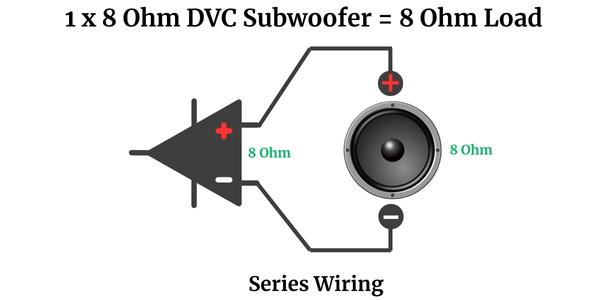
For this setup, your amplifier should ideally be stable at 8 Ohms. However, amplifiers stable at lower impedance levels, such as 4, 2, or 1 Ohm, will also be compatible with this setup. As always, it’s crucial to cross-check your amplifier’s stability ratings to ensure it can handle the load impedance and deliver an optimal performance.
2 x 8 Ohm SVB Subwoofers – Wiring Diagram
When dealing with multiple Single Voice Coil (SVC) subs, understanding how different wiring configurations impact the total load impedance is key to creating a superior audio system. In this section, we will examine the wiring diagram for two 8 Ohm SVC subs wired in parallel.
Option 1: Parallel Wiring – 4 Ohm Load
Parallel wiring involves connecting the subwoofers side by side, which effectively reduces the total load impedance across the system. So, when you wire two 8 Ohm SVC subs in parallel, the combined load impedance is halved, resulting in a 4 Ohm load.
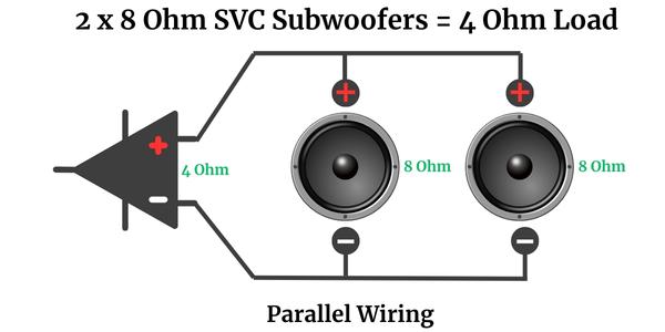
For this configuration, the amplifier you use should ideally be stable at 4 Ohms mono. That said, amplifiers that are stable at lower impedance levels, such as 2 or 1 Ohm mono, will also work with this setup.
As always, it’s essential to verify your amplifier’s stability ratings to ensure that it can comfortably handle the load impedance. This will prevent potential overheating or damage to your audio equipment and ensure optimal performance.
Wiring Diagram for Subwoofer
Understanding the intricacies of subwoofer wiring is a vital step in amplifying your audio experience. Our comprehensive guide on with additional Wiring Diagram for Subwoofer was designed to demystify the process of wiring your subwoofers correctly.
We offer various configurations, from Single Voice Coil (SVC) to Dual Voice Coil (DVC) and 1- to 8-Ohm impedance, each with its unique wiring needs. The details provided in each diagram should help you understand the impact of different wiring options and their resulting impedance loads.
Remember, the goal is to match your subwoofers and amplifier correctly, ensuring you attain the optimal performance from your audio equipment. By understanding these wiring diagrams, you are now equipped to navigate the world of subwoofer wiring effectively, ensuring you unlock the full potential of your sound system.

I am a passionate and skilled car audio enthusiast with 15 years of experience in the industry. My journey started when I replaced my first set of factory car speakers, sparking a deep love for high-quality sound. Since then, I have worked as a representative for renowned brands like Kenwood and Alpine.
With a background in both retail and distribution, I have developed a comprehensive understanding of the car audio market. Currently a certified (MECP) installer in the Mobile Electronics industry, my expertise lies in delivering top-notch audio installations. My knowledge, coupled with my genuine passion, makes me the go-to professional for all car audio needs.


